Category: Uncategorized
Moving to a new place
Thank you, everyone, for following my blog.
As I am beginning to move to more serious endeavors, especially in establishing new working grounds, I am not continuing to post on this blog, and eventually close this within six months.
However, all the posts I made here were already migrated to this new blog of mine, and have new posts as well:
https://mathcadbimthingys.technikstudio.com
And I will be posting new things on the above blog. So if you have any questions regarding the contents of the posts and other related matters, please do so in the above blog.
Meanwhile, I will still be answering unanswered comments before I close this blog, so please wait for the reply (it will be a long wait though, sorry for that).
Lastly, let me take this opportunity to thank you all who read and follow this blog. I was delighted to know that my posts were of great help in your Revit API programming journey.
See you at technikstudio.com.
Essential items for creating a WPF window for Revit API plugins (Revit API+WPF Series 2/3)
In this second part of the series, we will discuss essential items to apply when creating WPF windows.
In order to proceed, make sure your plugin project is capable of creating WPF windows. If not, you better create a project template with WPF functionality and create another new project. Then create a WPF window. In this case, make a window and name it viewThisWindow.xaml.
To make a WPF window work on its stable condition inside Revit, the following minimum recommendations are to be followed.
The window must be disposable
WPF windows are not disposable by default, so I recommend every WPF window be disposable. To do that, in the viewThisWindow.xaml.cs, set this on the line of the class declaration:
public partial class viewThisWindow : Window, IDisposable
The IDisposable interface will enable us to use the using() statement later on.
Implement the IDisposable interface to be able to create the Dispose() function inside the class, then input this line inside the function:
public void Dispose()
{
     this.Close();
}
This will force the window to close when the using() statement has done its work, especially when the operation is cancelled.
The window does not need maximize and minimize buttons
When working on a modal window, for most instances, it must only have an executing button (i.e. OK button) and a canceling button (i.e. Exit button on the upper right hand side of the window), and the minimize and maximize buttons are disabled.
Create a button inside the window and label it “OK”. Then make this button the default button by ticking the button’s IsDefault property from the properties window.
Addendum: After creating the OK button, double-click it to create an event, and in the event function that was created (somewhat like Button1_Click()), insert this line:
this.DialogResult = true;
This will help closing the window and tell the program that the window is successfully closed.
To disable the minimize and maximize buttons, first copy the following code and paste it inside the viewThisWindow class above the viewThisWindow() constructor.
[DllImport("user32.dll")]
internal extern static int SetWindowLong(IntPtr hwnd, int index, int value);

[DllImport("user32.dll")]
internal extern static int GetWindowLong(IntPtr hwnd, int index);

internal static void HideMinimizeAndMaximizeButtons(Window window)
{
      const int GWL_STYLE = -16;

      IntPtr hwnd = new System.Windows.Interop.WindowInteropHelper(window).Handle;
      long value = GetWindowLong(hwnd, GWL_STYLE);

      SetWindowLong(hwnd, GWL_STYLE, (int)(value & -131073 & -65537));
}
Then in order for this to work, create a SourceInitialized() event function.
To create this event function, select first the window itself in the XAML design window, then in the Properties window, click on the Event Handler window (the lightning-like icon located on the upper right). Go to the SourceInitialized event and double-click on the space adjacent to it. It will automatically create an event function with the _SourceInitialized inside the .xaml.cs file.
Inside this function insert the following line:
HideMinimizeAndMaximizeButtons(this);
This will hide the minimize and maximize buttons before the window shows up on the screen.
Note: There is another event function that is Loaded() but SourceInitialized() event function runs in between the constructor and the Loaded() function. Loaded() is dedicated to other things when the window is loaded and it is not the best location to execute HideMinimizeAndMaximizeButtons().
It must be always on top of the Revit application
To be able to be on top of the Revit application, we must also insert these lines to our plugin class:
using (viewThisWindow view = new viewThisWindow())
 {
      // the following two lines let the Revit application be this window's owner, so that it will always be on top of the Revit screen even when
      // the user tries to switch the current screen.
      System.Windows.Interop.WindowInteropHelper helper = new System.Windows.Interop.WindowInteropHelper(view);
      helper.Owner = proc .MainWindowHandle;
     ...
 }
Notice that we just used the using() method here. As you all know, using() can only be used when the class that you want to create is disposable; that is, the class is derived from the IDisposable interface and there is a Dispose() method inside that class. Anything done inside the Dispose() function of the class will be executed once using() has done its job.
And as an option, we un-tick the ShowInTaskbar property so that the icon of this window won’t show up in the taskbar.
Alternatively, you may just use these lines when you are loading just one WPF window inside your plug-in.
// System.Diagnostics.Process proc = System.Diagnostics.Process.GetCurrentProcess();

using (viewThisWindow view = new viewThisWindow())
 {
      System.Windows.Interop.WindowInteropHelper helper = new System.Windows.Interop.WindowInteropHelper(view);
      helper.Owner = System.Diagnostics.Process.GetCurrentProcess().MainWindowHandle;
     ...
}
Create Project and Item Templates in Visual Studio (Revit API+WPF Series 1/3)
In this three-part series, I will be tackling about proper basic integration of Windows Presentation Foundation (WPF) in your Revit API plug-ins using C# .NET.
For the first part, we will discuss creating project and item templates that we will use to create new projects with WPF functionality. For the item template, however, the objective is to be able to create plug-in executable classes without repeatedly creating lines common to your coding workflow.
Creating a Project Template
Visual Studio does not provide a class library project template that we can use for our WOF-ed plugins. So we need to create it. We will be starting to create a project template from a WPF application.
1.) From the File menu, create a new project. On the left panel, select either C# or Visual Basic, and from the center panel, select WPF Application (see figure below).
Name your project appropriately, (in my case, it’s Revit API with WPF), and then click the OK button.

Initially, the new project is created like the figure below. There are files created here that we really do not need, so we have to remove them.

2.) Delete the files MainWindow.xaml, App.xaml and App.config. All subsequent files will be deleted automatically.
3.) Let us add the reference files we need for creating new Revit API plugins.
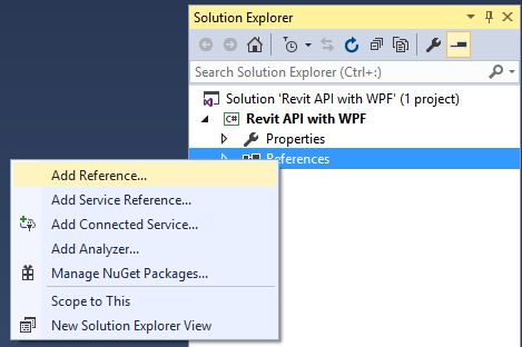
From the Solution Explorer window, right-click on References, and click Add Reference…
4.) The Reference Manager window as shown below will open. Click on the Browse… button.

5.) Browse to your Revit application location, and select the files RevitAPI.dll and RevitAPIUI.dll. Click on the Add button when done. Then on the Reference Manager window, click OK.

Try to expand the References item from the Solution Explorer window, and we can confirm that the files were added.
Everytime we create a new Revit plugin project, these files will be included in our project. But most of the time, these files post a warning saying that their location is not found.
To enable the location of these files to be always found, let us proceed to the next step.

6.) In the Solution Explorer window, right-click on the project name, and select Properties… and in the properties window, select the Reference Paths item.

7.) Click the ellipsis button on the upper right hand of the window, and browse for the folder where the reference files we just added are located.
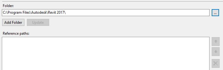
Click the Add Folder button. When we add the folder, Visual Studio will recognize the location of the reference files, and the warning icon will not show up anymore.
In addition to this, whenever we update these reference files to newer versions, we will just re-locate the folder (if in case we update the files to a version say Revit 2018, we can just change the text 2017 to 2018 and click the Update button).

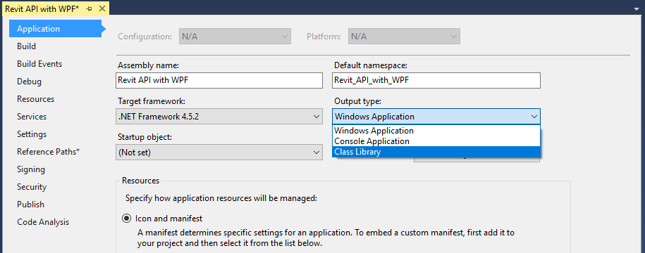
Let us set the output type of this project template. Since we are creating a project template which is a class library, let us set it to a class library.
8.) In the same window, switch to the Application tab. Set the Output Type to Class Library.
Close the window if you wish.
9.) Compile the project. The compile must be successful.
Next, we need to change one property from the project, but we will not do this inside Visual Studio.
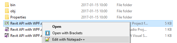
10.) Open Windows Explorer and locate the project. Right-click on the project file (the one with a .csproj extension), and open the file with Notepad or any text editor you have (mine is with Notepad++).
11.) From the text editor, look for the line with a <AssemblyName> entry. The entry must be the same as the name of our project.
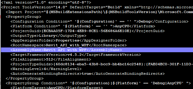
Change the name with $safeprojectname$.
We do this so that whenever we create a new project, the assembly name will always be the name of our project. If we do not, the assembly name will always be the name of the project template.

12.) Save the file in your text editor.
When we do that, Visual Studio will prompt like the window show below.
Click on Reload to reload and update the project file.

Now the necessary basic settings are done, we can already export the project to a template.
13.) From the File menu, select Export Template…

14.) Make sure the template type is set to Project Template. Then click the Next> button.

15.) In the Select Template Options window, give an appropriate template name and template description.
Optionally, you can attach icon and preview images for the template.
Leave all other options as is.

16.) Click on the Finish button to create the project template.
The File Explorer will open and show us fhe location of the created template. Close this window when done.

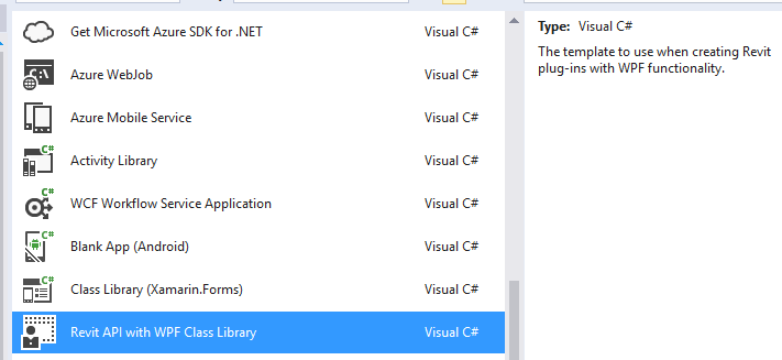
17.) Try to create a project using the project we just created.
Create a new project from the File menu, and from the template panel, check if the project template is included. If included, select the template and press the OK button.
18.) Look at the Solution Explorer window and check the reference files are added and without warnings.
Also, try to open the Properties window of the project, and from the Applications tab, check if the assembly name is the name of our project name.
When things gone well, we need to check one more thing.
Let us try to add a WPF window.

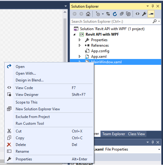
19.) Right-click on the project name in the Solution Explorer, and then from the Add item, select Window…

20.) The template panel must show templates with the (WPF) text.
Select Window (WPF), give it a name, and press the Add button.

Now our template is also capable of creating WPF windows.

Creating an Item Template
Although this has nothing to do with WPF, we take advantage of this procedure because we also need to create new plugin classes compliant with our coding workflow.
1.) Reopen the project template project we created earlier.
2.) Right-click on the project name from the Solution Explorer. From the Add item, select New Item…

3.) From the middle panel, select Class. Give the new class an appropriate file name, and click on the Add button.

3.) Copy the code on the figure below.
To reduce the typing effort, we do the following sub-steps.
Since the class derives from IExternalCommand interface class, input IExternalCommand after the class name separated by a comma. Press Ctrl+. (period) and select Autodesk.Revit.UI to add the reference class.
Right-click over the IExternalCommand base class, and from the context menu, implement the IExternalCommand interface.
This procedure will add the Execute function inside the class.
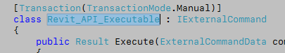
In the Execute function, add the other set of code as shown below. Also, add the other lines with the using statement and the Transaction attribute above the class declaration.
The code inside the Execute function may differ to your liking.

4.) Let us change the class name to comply with the template settings. Select the class name and replace it with $safeitemname$ as shown below.

5.) Save the file. Then from the File menu, select Export Template…
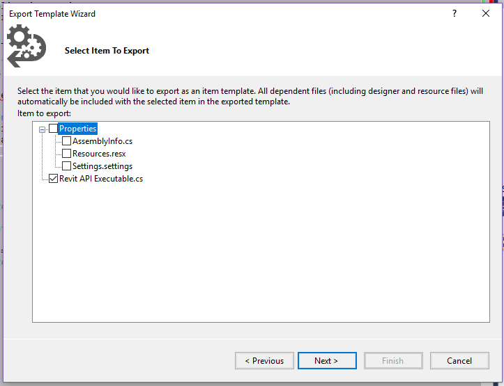
6.) From the window, select Item Template, then click Next >.

7.) In the Select Item to Export window, check on the file we just created. In this case, the Revit API Executable.cs file.
Click Next > afterwards.
8.) In the next window, we can add reference files necessary for our item template. Since we do not need any, just click Next >.

9.) In the next window, enter the appropriate template name, description and images if needed.
Click the Finish button when done.

Let us see if the item template will appear in the item templates list.
Before we proceed, I recommend to re-open Visual Studio in order for the new item template to be loaded properly.
10.) Open the test project we created earlier. Try to add a new item.
Once the window is opened, we can see that our item template is already loaded in Visual Studio.
Select the template, give an appropriate file name, and click Add.

The new class file will contain all the code we entered during the creation. Also, we can see that the class name is the name of the file.

So there you have it.
If you have any questions, feedback or comments regarding this post, please make sure to post them in the comment section below.
Celery: A new package for Dynamo
Just recently I published a new set of Dynamo nodes into a package called Celery.
While Rutabaga is a package of various useful nodes built with Zero Touch, Celery contains nodes built with custom user interface using WPF (Windows Presentation Foundation).
The reason for building these nodes in Celery is to provide you a better way to access data and manipulate outputs.
While as of this time there are only three nodes in the package, I will be expanding it later when I believe there are other needs to be addressed. For the meantime, here are the notes regarding their uses.

List Item Selector
This node enables you to select an item from a list passed through its input. The type of input may be anything as long as it does not include a nested list. It can be a list of numbers, integers or strings. When the nodes is unable to determine the type of input, it will output the selected item as a string value.
Since the types of input that it can read are very limited, I will broaden this area and make sure it can provide output as how its type should be.
Revit Parameter Selector
This node is derived from the List Item Selector node. The only difference is that it only allows a specific type of input by a Revit Element.
It extracts all the instance parameters of the element in the input. The output is the name of the parameter selected from the drop-down.
This is very best to complement with the Revit.GetParameterValueByName and Revit.SetParameterValueByName nodes already provided in Dynamo.
The reason for creating this node is to enable you to select a specific parameter name when you do not have to type or provide a string input to the Revit.GetParameterValueByName and Revit.SetParameterValueByName, especially when you want change the values of these inputs.
Input-bounded Number Slider
Many of you might wonder why there is a need for this node. The need for this node came when I was testing a geometry that changes with a range of numbers that are limited from a number of items in a list, which changes most of the time.
The integer slider and the number slider come without inputs. You need to input yourself the lowest and highest numbers as ranges on the fields provided. While they are the basic things you need in a slider, sometimes you want inputs you are unable to control. You would want inputs that are coming from the outside. This is when this custom node comes in.
You provide numeric inputs regardless of which is bigger or not. When the left range is bigger that the right range, the output value decreases when you move the slider to the right. Also, it also lets you select which type of output you want to have, either as an integer or a floating-point number. When you select the floating-point number, it even lets you set the decimal places.
As of this writing I noticed that I forgot to provide a step value. I will be updating the node to avail this functionality on its future release.
Please comment for any bugs or suggestions regarding this package.
Thank you very much!
Rutabaga for Dynamo
This year I have just developed a new set of nodes in Rutabaga.
Majority of these nodes are made for use in our office, but it is a great thing to make it public and let Dynamo users use and evaluate them.
Rutabaga nodes concentrate on linked documents and interference checks. Nodes that extract elements from its ID are the most important ones in interference check because as of Rutabaga’s release time, nodes that are available in the Dynamo package did not work properly. So I created four nodes made for it.
The new update as of this writing time is in 2016.2.9 version. Although I released seven more new nodes, I don’t know why the extension could only read five of them. I will be carrying out this issue and hopefully release the updated version within this week.
Below are the details of the nodes and its uses.
Revit.ElementFromId(Document)
Just like I had stated earlier, the reason of creating this set of nodes is that other nodes of the same purpose did not work properly. The other reason is since interference checking nodes are also created, there must be ID reading nodes that come with it, otherwise it is not a interference checking package at all. All other nodes required with this package are already available in Dynamo.
There are four nodes related to this in the package. One is reading from an integer ID, another is from a unique ID. The other two function just the same as the first two, but it has another argument called Document.
The first two read the element Id from the current document, while the other two read the ID from the document connected to them.
Revit.LinkedDocuments
This node reports all the linked documents inside the current project, as well as their paths and their positions. The first two outputs report as a type output, while the last output is an instance output.
The two type outputs just report what are the links in the documents, and their paths. So each data output should be unique. The position output, however, as an instance output, reports position of any instances of the link to the project. There maybe two or more instance for every type linked, so the number of instances and types may not be equal, but the number of instances must not be less than the number of types.
(I am still working on the type of the instance per position to output, so please wait for the fix.)
Geometry.IsPointInsideLoop
This node lets you determine if a point is inside or outside a loop of points on a counter-clockwise direction. You can also tell the node if the loop of points represent a hole, and the points will be read at a clockwise direction.
Vectors.TurnLeft/Right/AtNormal
These group of nodes is pretty straightforward. It will just return a vector turned 90 degrees left or right rotating along Z-axis with reference to the direction of the input vector. When the nodes with AtNormal option is used, the output vector will be when rotating at the given axis vector.
X.O
Simply put, a carrier or memory node that is very useful for Dynamo scripts with enormous amount of nodes used. Use this node when you want to bridge some parts of the script with outputs from nodes which you want to maintain, as well as tidying up the script. This node can also be used when you want to pass temporary outputs for tests.
Early morning at Murano 3201 December 3
I had my very first session at Autodesk University, yes it is 2015, and at this room inside The Venetian Hotel in Las Vegas, I had made a connection with the audience; of course they were those who pre-registered at my session. Although not all of them came, I was so delighted that were still about three-quarters of them came. I don’t know how will I thank them. I just hope that they learn something from me. And if ever I will be given a chance again to do the speaking at AU2017, I would like to do it again. This time, it will be better.
That Barker
But there is someone that I am most thankful for.
This man just did the best invites and calls outside Murano 3201 before my session time. I really appreciate his dedication to his job. I am somehow so grateful for his efforts to call the people who registered at my session. I can hear his voice from inside and somehow made myself do the best of me as he was just too active at his work.
I want to thank him to the fullest, but I just couldn’t remember his name.
To those who attended my session and the other sessions after mine, please tell me even his name if ever you know.
Thank you very much!
The Responses
I have just read all of the responses. Thank you to all those who respond.
I cannot make excuses here, but I admit I have to really work harder at my speaking, especially my English. I just hoped that I got to be exposed more often on this. But I have to start it first at a Japanese environment since I am working here in Japan and of course, the audiences are all Japanese. If there are even any small opportunities for me to have a presentation in total English and of course the audience are total English listeners and speakers, I would like to grab it.
And the other side of my feeling, I am also disappointed at the final result of my PowerPoint. Next time, I will make sure that I will present every detail on how to do things, if ever I will be entitled to a session that needs teaching. For instance, it is a Instructional Demo, right? I just can’t say what had happened during the final days of this presentation’s evaluation with my team.
To those who went away too early, I am just sorry for them. Although it always happens at AU…
Of course, there are many people who stayed ’til the end, and some of them commented positive ones. In fact, one of them said I had a great sense of humor. I really appreciate them and am so thankful to them. Nevertheless, my session was somewhat a success because of them. I would also like to collaborate with those people and share ideas with each other. I am not those guys like Marcello Sgambelluri or Nathan Miller who are total experts on both sides of presenting at AU. I could have my own style of talking; I just still have to discover that.
These sides benefit me to what I will become next AU.
.
Bridging Designer’s Template with Intuitive Families to your Working Template (AS9926)
As discussed in my session Revit++: More with Your Revit, More for Your Workflow session at Autodesk University 2015, when you use your designer’s template that contains intuitive families, you would want to use them in your project during the design development phase. But these intuitive families use instance parameters. Using instance parameters won’t be compatible enough in your schedules if you use schedules.
This post will provide you steps in converting your intuitive families to a more manageable “usual” families (those we are accustomed to) to be able to work smoothly with schedules, as well as eliminate discrepancies and inconsistencies that is presented in the intuitive families.
I would like to introduce here a program that is built for passing values from an instance parameter controlled family to its corresponding type-controlled twin family.

Did I say “twin”? Yes. Those two families must be identical with each other, the only difference being the other twin uses type parameters.
The prerequisites for using this program are mentioned below, and with them are steps to do it.
Creating the Twin Family
First, it is just simple. You have to save a copy of your existing family that has the instance parameters.
Then just make the instance parameters into type parameters.
But be careful! Some parameters will mess up your family when to switch them into type parameters, eventually tell you to delete the family when it fails to load in your project. This is a well-known issue especially when you try to convert an array parameter or a dimension parameter. Input some values before pressing the Apply button, and test them before loading it to your project.
Parameter Pairing
An optional effort but is handy when you started to use the program above to convert your families.
To have an idea of what to do, just list up all the instance parameter you used particularly in one family. Then create a type parameter to pair with every instance parameter you have. You just have to put a distinctive character or letter for your type parameter to differentiate it with the instance parameter.
For example, if you have an instance parameter that is named “Opening Height”, you create a type parameter that has a name such as “T Opening Height”. Remember to keep the same variable types!
Then use these parameters instead of re-assigning the existing instance parameters to type parameters. This is somewhat safer.
Using the Tool
Before using this tool, make sure you loaded all the twin families of all the instance-parameter-based families you use in your model.
1.) Select any instance of an instance-parameter-based family in your model. Click “Finish” button on the left side of the option bar to continue.
2.) A window like the figure above will appear.
All the editable instance parameters of the family instance you selected will be listed in the Instance Parameters column.
Take note that the letters enclosed in parentheses indicate what kind of variable the parameter is. The meaning of these letters are written below:
i = integer
d = real number
e = element id
s = string of text
n = none
3.) Select the type of the twin family from the Base Replacement Type area. All the editable type parameters of the selected family type will be listed in the Type Parameters column, with the kind of variable similar to those in instance parameters.
4.) Select a pair of parameter by selecting one parameter from the instance parameter list and another from the type parameter list.
Make sure the “Pair->” button will be highlighted. If not highlighted, make sure that the parameters you selected have the same kind of variable.
5.) Click the “Pair->” button. The selected parameters will be listed on the Paired Parameters column, and they will be removed from their respective columns.
6.) Repeat 4 and 5 to create other pairs of parameters.
7.) To remove a pair item from the Paired Parameters column, click an item and click the “<-Unpair” button. This will remove the item from the list, as well as return the parameters to their respective columns.
8.) When you listed enough items in the Paired Parameters column, it is time to designate a type naming format.
Select an item in the column and click “Add to Naming Format”. This will automatically add a string of text to the text entry.
9.) To add a character in the naming format, add it between the } and { characters. Adding between the { and } will damage the format and will yield to unexpected results in your family type name.
10.) To save the pairing data for use later, click “Save Pair Data…” button on the lower left of the window.
11.) Click the OK button when all is done.
The Best Practice
When you are already decided to build and use your designer’s template and also want to switch to your usual working template for your design development phase and construction documents phase, it is better to create a new family derived from an existing family, so that later you can easily change the type parameters to instance parameters and test operate them without having the “unable to create” error message and eventually delete them.
On the other hand, if you don’t have that family you want to use, you can just create you own, but be sure you assign type parameters first to that properties of that family. Then you derive them and change to instance parameters.
A Brief Introduction
A good day to everyone.
Very lately I am being involved into some work where my mathematical abilities and logical thinking are put on a test. Some things are new, others are formulated through net researches, and some are learned from some genius people around me.
Firstly, I would like to post here things regarding Linear Algebra, geometric algorithms such as Concave Hull and Tangent Circle, verifying some great tips in geometry using Rhinoceros and Grasshopper, and a little bit of calculus.
Hope you wait for the upcoming posts.
Not the very least. To introduce myself, at present I am developing tools for Autodesk Revit using C# .NET, and previously for AutoCAD using ObjectARX. I could say I have extensive ability in finding solutions, but not so extensive in the knowledge of C++, Revit API and C# .NET, for I often work mostly under user requests. Recently, I integrate WPF into my new Revit API tools to have a sense of somehow future-proof user interface.
I won’t be putting here codes most of the time, but you may expect illustrations and maybe pseudocode of algorithms I made that I can share.
